• Skip to primary navigation
  • Skip to main content

SOLARIAN

Are you ready to discover?

  • About Us
  • Services
    • Due Diligence
    • Inspection & Certification
    • Project Management
    • Investment Consultancy
  • Career
  • Contact Us
  • English
    • Türkçe
    • English
    • Deutsch
    • Română
    • Español
    • Italiano

Genel

DGES, BESS and Grid Integration

As solar power plants revolutionize renewable energy generation, seamless and accurate integration into the grid is becoming a critical element to fully realize this potential. Battery Energy Storage Systems (BESS) compensate for the intermittent nature of solar energy, ensuring grid stability and increasing renewable energy penetration. Standards such as IEC TS 62933-5-1 define the technical requirements of this integration, while the Technical Specification guides concrete implementations. In this article, we will explore how BESS integrates with the grid, its impact on its stability and practical scenarios.

Network Stability and BESS

Frequency and Voltage Control

Grid stability requires frequency and voltage to be kept within certain limits, but variable sources such as solar power can challenge this balance. The soon-to-be-built Storage SPPs (SSPs) solve this problem with their fast response time. According to IEC TS 62933-5-1, the Power Conversion System (PCS) should respond to grid demands within 200 milliseconds and provide frequency regulation. In these cases, PCSs can compensate the grid by injecting or absorbing energy during sudden load changes. This offers a critical advantage, especially in regions with a high proportion of renewable energy and where grid stabilization is challenging.

Compliance with Network Codes

Technical Requirements and Standards

For BESS to work in harmony with the grid, compliance with local and international grid codes is a must. IEC TS 62933-5-1 standardizes requirements such as low voltage ride-through and reactive power support. According to Solarian’s technical specifications, the PCS’s grid connection tests must be completed and the system must be able to operate without disconnection during sudden voltage drops. For example, a BESS with a charge/discharge rate of 1C should be able to offer both reliability and flexibility by instantly adapting to the demands of the grid operator.

The connection and compliance criteria for SPPs with Storage offered by TEİAŞ in this process are as follows.

GRID CONNECTION AND COMPLIANCE CRITERIA FOR ELECTRIC STORAGE FACILITIES-30122024 (PDF)Download

Microgrid and Island Mode

Independent Energy Systems

BESS not only supports the main grid, but also emerges in microgrid and island mode applications. The combination of solar power plant + BESS can become an independent source of energy during grid outages. It can thus enable a solar power plant to be self-sufficient during night hours or in emergency situations. The electrical safety tests of IEC TS 62933-5-1 ensure that such systems remain stable even when operating off-grid. When the requirements specified in the technical specifications prepared by Solarian are met, a long-lasting and smoothly operating storage solar power plant can be designed and built.

Practical Application Scenarios

Real World Example

The impact of BESS on grid integration becomes clearer with practical examples. Let’s say a 10 MW solar power plant generates excess energy during the day; BESS stores this energy and transfers it to the grid in the evening when demand peaks. It also supports the grid operator by intervening within seconds during frequency drops (e.g. from 50 Hz to 49.8 Hz). According to Solarian’s technical specifications, with a lifetime of 6000 cycles and a Depth of Discharge (DoD) of 80%, a DGES system plays a role in grid services for 10 years.

Future and Conclusion

BESS and subsequently solar power plants with storage (SHPPs) contribute to the future of renewable energy by making solar power plants grid-friendly. Grid stability, flexibility and the ability to operate independently increase the value of these systems. Resources such as IEC TS 62933-5-1 and Solarian’s DGES Technical Specification provide the technical basis for integration.

For more detailed information about the regulations in Turkey, you can read our article on BESS’ Grid Integration and Regulations in Turkey.

You can contact us at [email protected] for your engineering needs regarding your GES with Storage (DGES) power plants that you are planning to build.

Basics of Battery Energy Storage Systems (BESS) in Solar Power Plants

Although solar energy is an unlimited and clean energy source, it is naturally intermittent. While energy production decreases at night or in cloudy weather, more energy can be produced than needed on sunny days. This makes the use of battery energy storage systems (BESS) mandatory to regulate energy supply fluctuations and ensure energy continuity.

BESS is a complex system consisting of multiple components. The main components are:

  • Battery Cells: LFP (Lithium Iron Phosphate) batteries are widely used in solar energy systems due to their long life, safe structure and thermal stability. According to the technical specifications, LFP batteries are preferred for systems with a capacity of 10 MW/14 MWh.
  • Power Conversion System (PCS): Provides DC-AC conversion, making the energy stored in batteries suitable for the grid.
  • Battery Management System (BMS): Controls charging/discharging processes and prevents overcharging or discharging to ensure healthy and efficient battery operation.
  • Energy Management System (EMS): Optimizes the energy flow by integrating the solar power plant with the BESS.

Introduction to IEC Standards

The design, safety and performance of energy storage systems should be determined in accordance with IEC standards. The main relevant standards are:

  • IEC 62933-1: Defines terminology for battery energy storage systems.
  • IEC 62933-2-1: Describes unit parameters and test methods. These standards ensure that quality and safety standards are maintained in the design and implementation of BESS.

BESS Integration with Solar Energy

BESS performs the following critical tasks in solar power plants:

  • Grid Stability: Compensates for sudden power fluctuations and stabilizes the grid frequency.
  • Peak Limiting: Helps reduce electricity prices by supporting the grid during peak consumption hours.
  • Frequency Control: BESS stabilizes frequency fluctuations, ensuring stable energy supply.
  • Renewable Energy Utilization Efficiency: Stored energy can be used when demand increases, enabling more efficient utilization of renewable energy resources.

Conclusion

Battery energy storage systems in solar power plants are critical technologies that ensure energy continuity and grid stability. Through the use of LFP batteries, compliance with IEC standards and energy management, BESS increases the efficiency of solar power systems and supports the achievement of sustainable energy goals.

If you need engineering for your storage solar power plants, you can contact us at [email protected].

Emerging Technologies and Trends in Solar Power Plant Storage Systems

Battery Energy Storage Systems (BESS) in solar power plants will shape the future of technology. Because new battery types, artificial intelligence integration and hybrid systems increase the performance, efficiency and sustainability of BESS. While existing standards such as IEC 62933-2-1 support these developments, industry trends are pushing the boundaries of energy storage. In this article, we will discuss the innovations in BESS technology and the future direction of integration with solar energy, even though there is no licensed power plant installed in Turkey yet (April 2025).

Next Generation Battery Technologies

Solid State and Flow Batteries

While Lithium Iron Phosphate (LFP) batteries are currently widespread, solid-state batteries and flow batteries look set to be the talk of the future. Solid-state batteries offer higher energy density and safety by using a solid material instead of a liquid electrolyte, and more easily pass the thermal runaway tests of IEC 62619. These technologies promise longer-lasting and flexible storage solutions for solar power plants.

Optimization with Artificial Intelligence

Evolution of EMS and BMS

Artificial intelligence (AI) is transforming BESS’ Energy Management System (EMS) and Battery Management System (BMS). The performance parameters of IEC 62933-2-1 (e.g. round-trip efficiency of 98%) can be optimized in real time with AI. For example, in a power plant, AI-powered EMS can make energy distribution 10% more efficient by predicting peak demand hours. This means both cost savings and grid stability. In fact, we can say that technology and software will be the other business line that will drive the development of storage systems.

In the future, the BESS is expected to work with hybrid systems, rather than on its own. Excess electricity generated by solar power can be converted into hydrogen (H2) and stored, ideal for long-term energy storage. While the environmental guidelines of IEC TS 62933-4-1 accommodate the low-carbon production of hydrogen, a 10 MW system in the Technical Specification can be expanded with a hybrid approach. For example, short-term storage with BESS during the daytime, while excess energy can be converted to hydrogen and stored for weeks. This offers a solution to the seasonal fluctuations of solar energy.

Global Trends and Forecasts

Capacity Expansion and Innovations

The energy storage market is growing rapidly; the International Renewable Energy Agency (IRENA) estimates that global BESS capacity will double by 2030. This growth is supported by the commercialization of new technologies. For example, solid-state batteries are expected to enter mass production in 2025, or AI-based systems will become widespread. With these trends, solar power plants will become more reliable and scalable.

Future Vision and Conclusion

The future of BESS focuses on maximizing the potential of solar energy through technological innovation. Solid state batteries, AI optimization and hybrid systems are ushering in a new era of energy storage. IEC standards drive these developments, while documents such as the Technical Specification lay the groundwork for practical applications. Energy storage will be a critical issue in the future.

If you need engineering for your storage solar power plants, you can contact us at [email protected].

What is Solar Simulator (Flash Test) in Solar Panel Production?

Solar simulator is a critical measurement system that determines the current-voltage (I-V) characteristics of photovoltaic (PV) modules, determines the power and current class by performing measurements on all panels on the production line for the electrical data on the product information label, and its features are determined by the IEC 60904-9 standard.

Solar simulators actually mimic sunlight in a laboratory environment and are used to determine the efficiency, power output and performance of solar panels. This information is critical to improve the design and manufacturing process of solar panels, verify compliance with standards and provide consumers with reliable information about the solar panel.

Solar panel parameters are measured under standard test conditions (STC). Standard test conditions under IEC 61215 for panel testing include;

Solar Panel STC Test Conditions

What parameters can we obtain from the simulation?

Solar Panel Power Measurement Results

  • Maximum power output (Pmax)
  • Maximum power point voltage (Vmpp)
  • Maximum power point current (Impp)
  • Short circuit current (Isc)
  • Open circuit voltage (Voc)
  • Series resistance (Rs)
  • Module efficiency (Eff)
  • Temperature coefficient

Solar Panel IV Measurement Results

Using the Solar Simulator we also obtain the current-voltage (IV) curve, which is used to determine the performance and electrical characteristics of the solar panel.

In IV results, we want the panel temperature to be 25 degrees. For this reason, there is also a climate sensor inside the IV device. Here, too, the temperature is expected to be close to 25 degrees. The IV device tries to measure itself based on the panel temperature. Even if the panel temperature is 25 degrees, if the environmental conditions are at low degrees, a low power panel can be detected as a result of IV.

Solar Panel IV Graph

Solar Simulator Working Principle

A solar simulator usually includes a lamp, a reflector and an optical system. The reflector is used to focus and diffuse light. The optical system is designed to sample the light and direct it to the target. It is thus possible to simulate sunlight in various conditions and test how certain materials or devices will behave under sunlight.

Reference Cell in Solar Simulator

In solar simulators, the reference cell is a measuring device used to ensure the accuracy and stability of the sunlight produced by the device. This cell has a known electrical output and accurately measures the intensity and spectral distribution of sunlight.

Calibration of reference cells is a very important issue. The reason for this is to accurately adjust the output of the solar simulator device and to obtain reliable results. These cells standardize the performance of photovoltaic devices and enable comparative analysis.

So what are our references when measuring in the Solar Simulator?

Reference Panel in Solar Simulator Devices

There are important considerations in selecting the reference panel used in solar simulators, such as the intensity and spectral distribution of sunlight. The reference panel ensures that the output of the solar simulator is set correctly and is used to ensure the accuracy of the measured data.

What are Gold and Silver panels and why are they used?

In solar simulators, the terms “silver panel” and “gold panel” are often used for calibration standards.

Silver Panel A silver panel is a lower cost version of a standard reference cell or reference panel. It is often used in routine calibration of solar simulators. It is designed to provide the standards used during solar simulation.

Gold Panel Gold panels are more sensitive panels that allow for higher quality control and more accurate measurements. Gold panel is especially preferred in industrial applications that require high precision. These terms are used to refer to the different levels of reference standards used in the calibration of solar simulators.

In order to obtain a healthier result while measuring, there are some points that we should pay attention to in the Solar Simulator device. These are

  • Spectral Distribution: The lamps used in the simulator must accurately mimic the spectral distribution of sunlight. This is important to simulate real-world conditions as closely as possible.
  • Light Intensity: The light intensity that the simulator can produce should be close to the intensity of real sunlight. This helps to more accurately determine how the panels will perform in real-world conditions.
  • Environmental Conditions: The temperature, humidity and other environmental conditions of the environment in which the simulator is used must be under control to ensure that the panels are tested more closely to real-world conditions.
  • Calibration The simulator needs to be calibrated regularly. This ensures the reliability of the test results.
  • Data Analysis: It is important that the data obtained is analyzed correctly. This is necessary to properly evaluate and improve the performance of the panels.
  • Safety Safety precautions must be taken and the simulator must be used appropriately. It is important to use the necessary protective equipment to prevent exposure to light.

Author:

Kardelen Kucuktas

Safety, Testing and Performance Standards for Solar Energy Storage Systems

Battery Energy Storage Systems (BESS) are a critical component that ensures energy continuity and grid balance in solar power plants. However, these systems must comply with certain standards and test procedures in order to operate safely. Fire risks, overcharging/discharging and thermal runaway events in batteries can create serious safety issues. Therefore, it is of great importance to design, test and implement safety protocols for BESS systems in accordance with international standards.

Safety and Fire Risks in BESS Systems

Safety in battery systems is mainly concerned with fire risks and battery failures.

  • Thermal Leakage: When batteries start to overheat, a chain reaction can occur and lead to battery fires.
  • Overcharge and Discharge: These are conditions that shorten battery life and increase the risk of explosion.
  • Short Circuits and Electrical Faults: Lightning, high voltage surges or equipment failures can cause serious hazards to battery systems.

The main safety standards to minimize these risks:

  • NFPA 855: Sets fire safety standards for energy storage systems.
  • UL 9540A: Defines thermal runaway test procedures.
  • FM Global 5-33: Provides guidelines for the safe installation of energy storage systems in industrial buildings.

Battery Management System (BMS) and Energy Management System (EMS) Role

Battery Management System (BMS) and Energy Management System (EMS) play critical roles in the safe and efficient operation of BESS systems:

  • BMS: Monitors the voltage, current and temperature levels of the batteries to prevent overcharging or discharging.
  • EMS: Manages the overall energy balance of the battery system and optimizes its integration with the grid.

Performance Tests and Acceptance Processes

Before a BESS system can be commissioned, it must undergo different tests.

  • Factory Acceptance Tests (FAT): Testing the system at the factory to check that it complies with standards such as IEC 62933-2-1.
  • Field Acceptance Tests (SAT): Evaluation of the system’s performance under actual charging/discharging conditions in the field where it is installed.
  • Thermal and Environmental Testing: Tests that measure the battery’s resistance to extreme temperatures, humidity and mechanical impacts.

Testing and Certification Processes within the Scope of IEC 62933 Series Standards

The following IEC standards are critical for the safe integration and use of BESS systems:

  • IEC 62933-1: Defines BESS terminology.
  • IEC 62933-2-1: Defines test methods and unit parameters.
  • IEC 62933-5-2: specifies safety requirements for electrical energy storage systems.

Overcharge, Overdischarge and Thermal Leakage Risks

  • Overcharge and Discharge Protection: Must be limited by voltage and current limits controlled by the BMS.
  • Thermal Leakage Protection: Fire detection systems, active breathing systems, active cooling mechanisms and appropriate battery design should be used.
  • Safety Procedures: Mechanisms should be in place to automatically shut down the system in unusual circumstances.

Conclusion

The implementation of safety, testing and performance standards in BESS systems is critical for the long life, efficient and safe operation of the system. Battery systems designed in compliance with IEC standards, NFPA and UL safety guidelines increase both investment security and guarantee continuity in energy supply.

If you want to get information about all these audit and control processes, you can contact us at [email protected].

An Article on Electricity Storage System Integration to Solar and Wind Power Plants

The main purpose of this article is to establish a storage facility and to support the network. GES/RES integration is the motivator for this, but in fact, it can be integrated into GES/RES production and can be made to benefit more from this production. How Does? Let’s set the technical parameters and move on to the analysis.

First of all, units and limits;

  1. “up to installed power”: Here we assume that the storage system is based on MWe (ie output power). In other words, the sum of the output powers of how many inverters there are in the storage system or the grid limit.
  2. MWh: Storage system energy. There is an energy stored in these products from Power *Time. No reference has been made to this unit, so we can determine it.
  3. MWp: Total power of solar panels used in SPP projects. It is a unit that everyone who reads this article is already familiar with.
  4. “up to installed power”: Here again, we assume that the MWe value of the SPP is referred to.
  5. The charging power of the batteries (MWp-MWe or just MWe) should not fill the total MWh capacity in less than 1.5 hours. Actually recommended at least 3-4 hours. If we take into account, we should have a maximum charging power of 666kWe for a 1MWh storage facility. Recommended range is 250kWe-300kWe for 1MWh storage.
  6. The discharge power of the batteries should not be shorter than 1 hour. This means a maximum of 1MWe for a 1MWh plant, but that’s the limit. In order for the system to be long-lasting, this value should be around 3-4 hours, that is, in the 250kWe-300kWe band.
  7. Usable Energy (DOD): Batteries are damaged when they are fully charged and completely discharged. More than 20% discharge, more than 80% charge is not recommended for lithium batteries (60%DOD). For LFP (Lithium Iron Phosphate) batteries, it is still not recommended to go below 20%, but it can go up to 95% (75%DOD) during charging.

After units and limits, we have two more parameters that will affect the financial part of the design;

  1. How much energy would we lose if the batteries were fully charged? (Unstorable energy)
  2. If we choose the battery group as too large, how much kWh of storage will not be used at all, but we will have to base it on CapEx in the financial model (inactive storage investment).

If we proceed through a SPP facility with storage installed in Burdur Turkey,

Let’s consider a 1MWe storage facility. This facility needs around 4MWh of storage to properly recharge/discharge. Considering that we have established a facility with 80% DOD (15%-95%), we actually need to install 5MWh in order to deliver 4MWh. For this reason, let’s take our installed storage capacity as 5MWh.

So, if we build a solar power plant with an output power of 1MWe, how many MWp DC power would be the right choice for us? We can determine this with a few simulations.

1MWe:1MWp = Storage not used at all

1MWe:2MWp (2x overload) = 18.4% of annual production is stored. An energy of 0.05% is also lost because the storage system is full.

1MWe:3MWp (3x overload) = 23.5% of annual production is stored. 14.56% is lost before being stored.

1MWe:4MWp (4x overload) = 20% of annual production is stored (Note the decrease compared to the previous overload). 30.69% is inert energy and is lost before being stored.

As seen in this technical scan, the installed power of SPP in storage facilities can reach very high values. Of course, technical parameters are not enough for investments alone. Values ​​to be considered are always financial (IRR, RoE, etc.) returns.

So how to optimize financial return? At this stage, many more parameters come into play, for example the aging rate of the batteries we call “State of Wear”. AC power, battery maximum charging power, battery maximum discharging power are repeatedly examined and reflected as CapEx/OpEx in financial models, according to the battery behavior parameters according to the number of cycles received from the battery manufacturer and the DOD. At this stage, the PV power is optimized again according to these expectations. At this stage, technical optimizations are carried out within the PV part itself and sensitivity analyzes are created.

For a correct integrated PV/Storage solution, more than 50,000 different simulations must be performed at the correct parameters and inserted into the financial model. Only in this way, an accurate dimensioning and projecting can be realized.

You can contact our team for storage design .

Ukraine Gilmaziv 12MWp Solar Power Plant Project

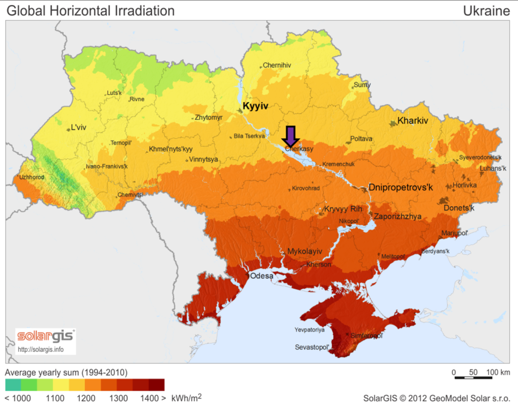
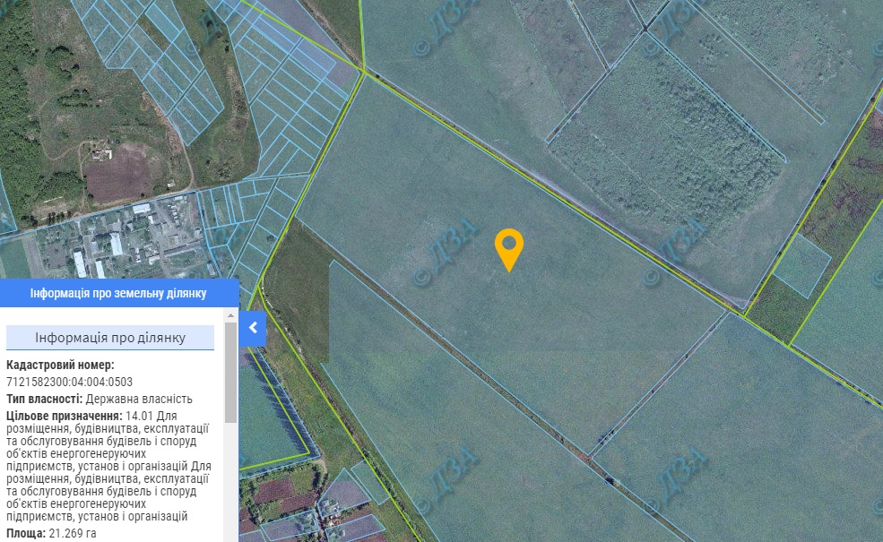
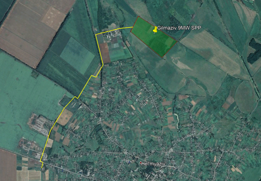
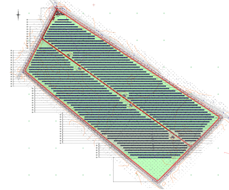
You can find the details of the developed solar power plant of 12MWp/9MWe below. The SPP is located in Gilmaziv / Ukraine.

The project consist of 12 SPVs. The zoning process has been completed.

It’s expected that the project will produce ~15.611MWh of energy in a year. Detailed PVSYST simulations can be downloaded at the end of this page.

Project details are as below.

Project Land:

Video of project area:

Project location:

Zoning complete parcel information:

Connection:

Video of road from the transformer to project area:

Approved Project (Can be changed afterwards):

Energy Yield Assessment:

PVSYST Energy Yield Assessment

Corporate Documentation :

Company Shareholding Structure

Land Lease Agreement

Connection Agreement

Technical Specifications on Connection

DABI/GASK Construction Approval

Power Purchase Agreement

Current Renewed PPA

Documents for TDD:

Approval of Land Management Project

Project Urban Conditions

Soil Test

Excerpt from Geokadastr

Excerpt from Land Registry

Approved Technical Documents for TDD:

1_Пояснювальна записка_Гельмязів

2_Генеральний план_Гельмязів

3_Архітектурно-будівельні рішення_Гельмязів

4_Електротехнічні рішення_Гельмязів

5_Конструкції металеві_Гельмязів

6_Проект організації будівництва_Гельмязів

How much revenue does the production problem in solar panels lose?

What is the ratio of the loss of income caused by the loss of the power of the solar panels to the power loss? Although this ratio is expected to be the correct proportion, the loss of production is more than the loss of power.

So how?

First, let’s look at a work we did last week.

I share the IV chart of 10 sample arrays in a SPP consisting of 160 arrays. You can see that the lines that normally need to overlap start from different short circuit currents and follow different characteristics. First of all, we see that the array is facing an incompatibility problem. The power within the power of the arrays converges to the lowest panel. A similar situation has occurred here.

When we look at the measurement values ​​after solar panels control, we see that the losses occurred after deducting the error margins and deviations. In summary, the 270W solar panels are moving between 250-260W. When we get the average of 160 series, we are facing a coverage rate of 95%. On average, solar panels are powered by 256W instead of 270W. This is a very serious difference. At the same time, there are various hot spots and production problems in the physical examination of the solar panels.

Now let’s go to production.

Have you noticed anything? On sunny days, the spread opens even further. In the IV measurements, the solar panels, which we found 95% productivity, fall to 87% in production. As the intensity of the radiation increases and the temperature increases, the internal resistance of the solar panels increases, the effect of the problems arising from the production increases, and the solar panels produce less than expected, and the solar panel which produces the least as it draws down the complete string.

Today, the only problematic panel in the strings consisting of 20-24 solar panels decreases the others. The field in which we conducted this inspection was a little more fortunate in terms of detecting this error, because they were able to determine the difference because there were also regular solar panels in the same facility. What if your entire facility is missing? The only way to find out is to inspect your facility.

Please contact us to check your facility.

  • « Go to Previous Page
  • Page 1
  • Interim pages omitted …
  • Page 6
  • Page 7
  • Page 8
  • Page 9
  • Go to Next Page »

SOLARIAN