• Skip to primary navigation
  • Skip to main content

SOLARIAN

Are you ready to discover?

  • About Us
  • Services
    • Due Diligence
    • Inspection & Certification
    • Project Management
    • Investment Consultancy
  • Career
  • Contact Us
  • English
    • Türkçe
    • English
    • Deutsch
    • Română
    • Español
    • Italiano

Genel

Pushing the Limits in Electroluminescence (EL) Testing of Solar Panels

How should the hand test be done? How much detail do we need in the EL photo? We were puzzled by many questions, such as, if we can take a photo to see what details we can see, we can see whether it complies with the quality guidelines in panel production.

The EL test journey also brought with it a lot of trial, error and learning.

In order to take an EL photo, you first need to know what EL is. EL is not just a photo you can take with equipment; you need to turn a solar panel into an electroluminescence (EL) source. In other words, we energize the solar panel and turn it into a UFO heater. “What do you mean?” I can hear you ask. Yes, we light the solar panel like a lamp to take this photo.

Since the photo is a long exposure, you apply this voltage for about 10 seconds, so nothing happens to the panel, but if you apply it for a long time during the test phase, you will burn the panel. Don’t try it yourself at home 🙂

After learning the technology thoroughly, we built our own small test station and started our first trials.

Düşük çözünürlüklü ve net olmayan elektrolüminesans EL fotoğrafı
Our first EL attempts (First photo of this page)

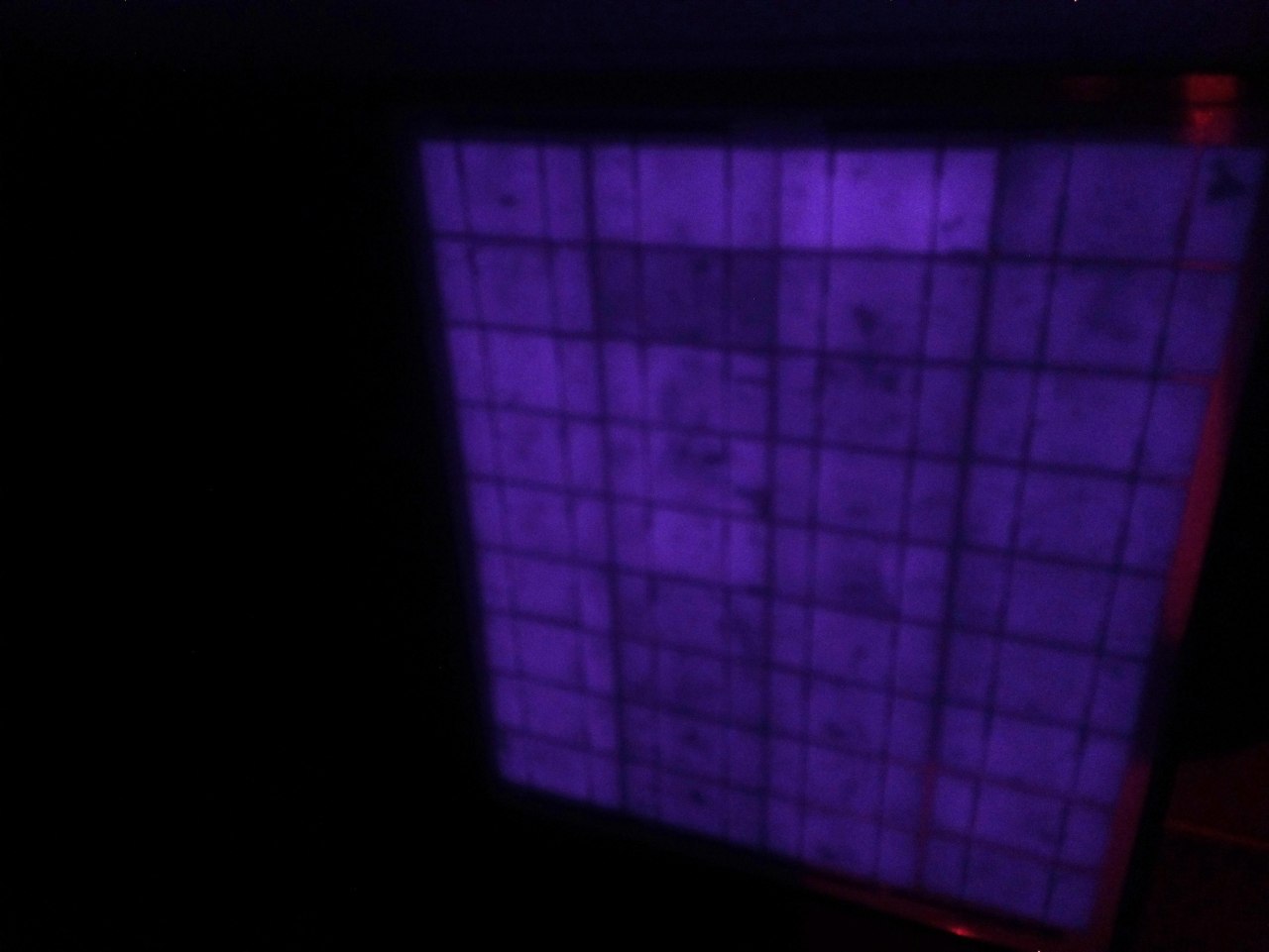
Even though this EL photo was not clear and did not have enough pixel detail, it was an indication that we were on the right step. We immediately went to the field and made our first test.

Sahada ilk Elektrolüminesans EL testi çalışmalarımız
First works on the field

One night we conducted our first experiments at the facility of a company where we regularly carry out O&M processes. The goal was to use RaspberryPi to push files to the cloud and process them there.

Raspberry Pi ile EL testi cihazı haberleşmesi
The pleasure of creating a wi-fi hotspot on Raspberry Pi and using it on iPad by connecting with SSH 🙂

At this stage, communication and machine learning technologies were ready to be used. The infrastructure was there, but the images were not of high enough quality. So how do we define quality? How high quality should an EL photo be?

We took the records of a factory capable of taking high-end EL photography as a benchmark.

Örnek bir fabrika EL test cihazının görüntüsü
Image of a sample factory EL tester

Our aim was to capture at least this image quality in the field. For this reason, a serious sensor/lens hunt started for us. Which sensor should we use with which settings? Which feature of which lens should we utilize? Which filters were necessary, we went on a long journey. In every EL photo we took, we looked for the next step, which I believe we have reached at some point. But the solution was not only hardware-based.

In addition to off-the-shelf EL hardware solutions, you also need a post-processing process to get the required values in the image, so it’s both a hardware and software problem.

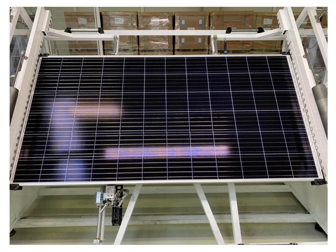
So where did we come from? Good question. See below the first and the last photo we took of the same panel.

İlk EL test fotoğrafımız
First photo of the test panel in the office (Same as the first photo of this page)
Güneş Panelleri İçin Elektrolüminesans (EL) Testi
Latest EL photo taken with Solarian’s EL tester (Click to see original version)

Isn’t the difference enormous? Where have we come from? Today, there is a very serious optical quality and optimization with software. We have a photographic technique that allows us to see even the finest details on the cell.

Moreover, our Raspberry device in the system can receive this data and send it to the cloud, where a python code analyzes and interprets it. Today, we developed the device you see above, we wrote the necessary photo manipulation codes and we are developing cloud applications. Maybe 5 years ago, these were dreams. Where is technology going?

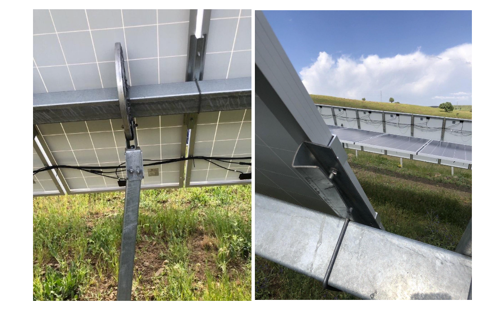
Do not damage the panel while mounting the panel. All will be revealed when we come to the EL test 🙂

You can fill out the form below to get information about our EL tests.

Employer Engineering in Solar Power Plants

It’s time to build a solar power plant and generate your own electricity. In this process, with our employer engineering service, we technically manage the entire process for you and help you get the best out of the facility you will build.

You can find our technical engineering service scope for SPPs below. If you have any questions about our scope of services, you can contact us here or send us an email.

1. Pre-Construction Period

1.1. Design Selection and Yield Analysis

Optimum shading distances, angle values, dead zones and the associated potential installed power values are determined based on the structure of the roof or terrain.

Çatı tipi güneş enerjisi santrallerinde çatıya panel yerleştirilmesi

The meteorological data set (radiation, temperature, etc.) required for SPP generation analysis is compiled. In order to create the data as close to reality as possible, 4 different data sets are utilized and sensitivity analysis is performed.

Çatı tipi güneş enerjisi santralleri için meteorolojik verilerin alınması

The biggest loss factor in rooftop SPPs is shading and shading analysis needs to be performed in detail. At this stage, we calculate shading losses by drawing both the obstacles on the roof (chimney, lighting, etc.) and geographical obstacles (mountain, tree, etc.) in 3D. Even in the same region, shading may vary according to the structure of the surrounding land. Since these will have a direct impact on production, their analysis should be done professionally.

Çatı tipi güneş enerjisi tesislerinde detaylı gölgeleme analizi

Land Solar Power Plant Generation and Shading Analysis with PVSYST

The equipment used in solar energy facilities (solar panels, inverters, etc.) vary technologically. These different technologies are evaluated and appropriate installed power values and design are analyzed.Çatı tipi güneş enerjisi yatırımlarında üretimlerin persantil cinsinden olasılıklarının hesaplanması

1.2. Financial Feasibility Study

A financial model that works in harmony with technical inputs is a strategic decision support tool for investments. In this respect, cost analysis is performed for all design alternatives. Bids received from EPC companies are included in the cost analysis and a project-specific financial feasibility model is built. Internal Rate of Return (IRR) and Net Present Value (NPV) results are calculated by running the model and reported to the Employer.

Çatı tipi güneş enerjisi santrallerinde fizibilite

Çatı ges lerde finansal fizibilite hassasiyet analizi

1.3. Control of Conformity of Technical Documents to Relevant Standards

Technical specifications are very important for a flawless installation application. After the project design studies are finalized, the compliance of the EPC and O&M technical specifications with the relevant standards for the SPP project is checked. It also clarifies the methodology to be used in calculating the project’s PR.

1.4. Approval of Final Projects

After the selection of the EPC, the projects to be drawn by the EPC are controlled and approved by us, and the approval of the projects by the EPC to the relevant institutions is supervised.

2nd Construction Period

Construction period engineering services are the processes that include the design and supervision of the processes that will take place during the investor company’s solar power plant investment and the commissioning of the power plant. In this way, it is aimed to minimize the risks and prevent possible problems that may occur in the long term. It also aims to take measures to protect the rights of the investor for possible legal processes.

2.1. Determination of Technical Quality Criteria with Reference to Relevant Standards

First, a SPP project kick-off meeting is held and a construction roadmap is created. At the same time, a responsibility matrix is created to prevent problems that may arise in the later stages of the project.

Contractor requests arising from problems that arise during implementation are examined. The technical compliance of these requests is checked and communicated to the investor, facilitating decision-making processes.

2.2 Solar Panel Production Process Factory Inspections

The most important equipment used in solar power plants is the solar panel. For this reason, it is important that its production is realized in accordance with the standards. Production controls of solar panels are carried out in two stages. At the first stage, product certification control is carried out. Factory inspections are then carried out during the production process.Güneş paneli üretim fabrikası denetimi 
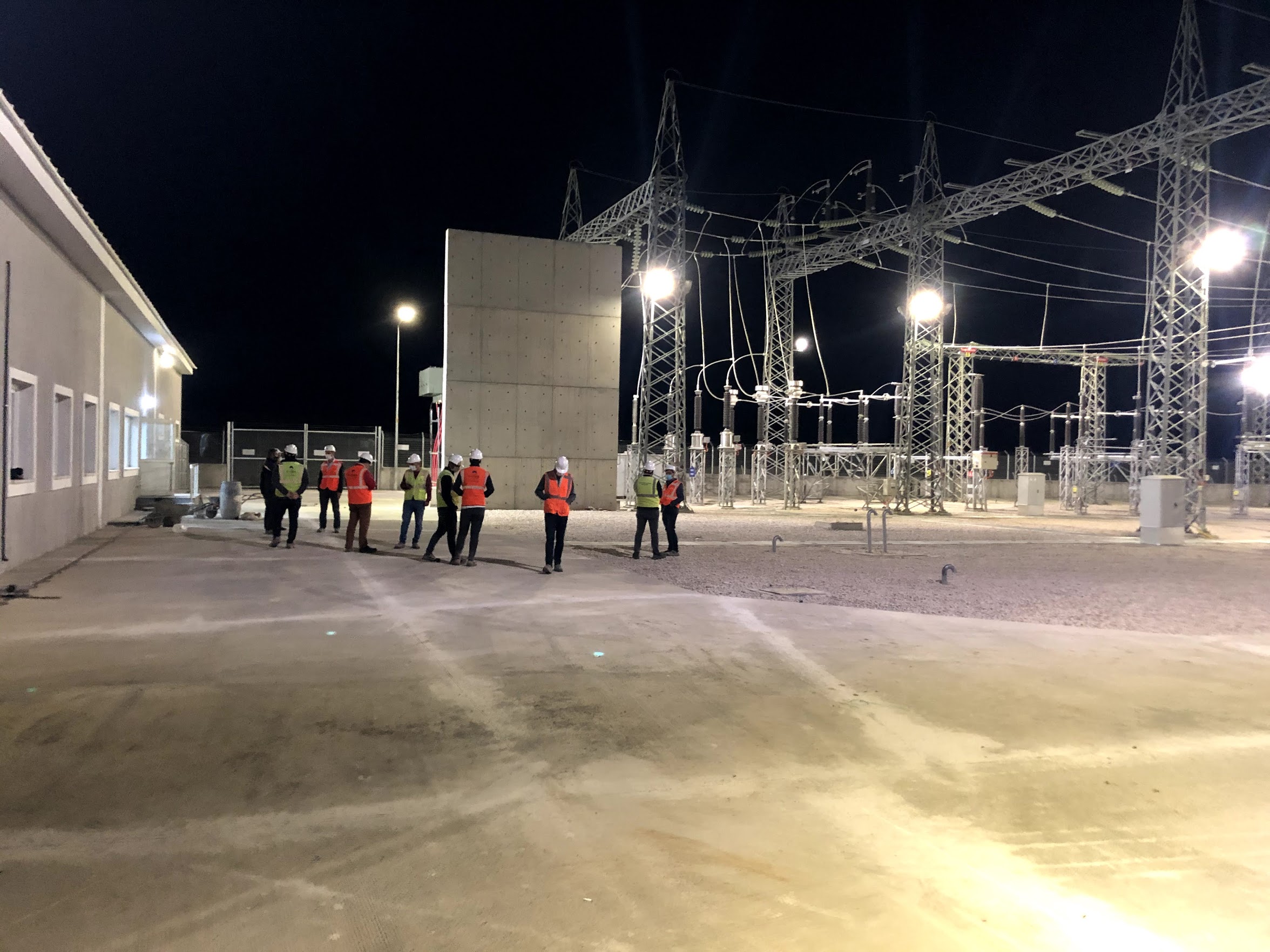
2.3. Inspection of Construction Processes

Regular on-site project audits are carried out for the healthy progress of the project from inception to acceptance. In this process, project progress is monitored according to the contract. Regular project visits are carried out during construction. According to the requirements of the EPC contract, construction and project progress is monitored in line with the planned schedule.

Alanlarında uzman bir ekip ile düzenli olarak tesis denetimi ve ziyareti

Quality controls are carried out during the production of incoming materials for the SPP plant and after shipment to the site.

Çatılarda kullanılan konstrüksiyonların kalite denetimi

Çatı konstrüksiyonlarında kullanılan malzemelerin kimyasal ve fiziksel analizleri

All construction and assembly works are carried out in a controlled manner, as any mistake in the assembly part may become irreversible in the future. The process is regularly reported and recorded from start to finish.

Düzenli olarak saha raporlaması

2.4. Commissioning Tests

In order to monitor and measure the performance of solar power plants, it is necessary to perform tests within the scope of IEC 62446 and IEC 60891. These tests are mainly IV-Curve (current-voltage) measurement, thermal tests, insulation test, grounding test and performance measurement. After the solar power plant is installed, these tests are carried out and it is analyzed whether the plant performs as expected. You can find a detailed description of the tests here.

A report containing all the tests is prepared. This report is also a risk table. According to the report, the findings are prioritized and presented to the EPC company. Warranty processes are put in place and a new business plan is created together with the EPC company to meet the necessary conditions.

Çatı tipi güneş enerjisi yatırımlarında termal testlerin gerçekleştirilmesi

Çatı tipi güneş enerjisi santrallerinde akım-gerilim IV testleri

3. Final Acceptance Tests (IEC 62446)

After at least 6 months of operation of the facility, a site visit is made and visual and electrical controls are carried out according to the standards. At the same time, performance measurements of the equipment are made and it is reported to the investor whether the conditions guaranteed by the manufacturer are met. Visual inspections check for physical defects, while electrical tests check production performance.

GES güneş enerjisi santrallerinde görsel denetim

Once the plant is in production, radiation data, production data and temperature data are processed and the overall efficiency of the system is calculated. With this calculation, the performance of the system is revealed. In the subsequent controls, degradation is also based on this data. This is a necessary data set to track any project-wide problem or excessive degradation of cells.

Güneş enerjisi santrallerinde performans testleri

4. Monthly Operating Reports (For 12 Months)

Once the plant is in production, radiation data, production data and temperature data are processed and the overall efficiency of the system is calculated. With this calculation, the performance of the system is revealed.

Çatı tipi güneş enerjisi yatırımlarında PR kontrolü

Çatı GES'lerde üretim ve gelir raporlaması. Kapamaların belirlenmesi. EPC sorumluluklarının belirlenmesi.

We are with you as your engineering team in the entire process from system design to operation.

Please contact us for information about our employer engineering service.

Safety and Risk Management in Battery Energy Storage Systems (BESS)

While Battery Energy Storage Systems (BESS) in solar power plants make renewable energy compatible and sustainable with existing grids, the safety and risk management of these systems comes to the fore. From fire risks to electrical hazards, the complex nature of BESS requires careful risk assessment. Standards such as IEC 62619, NFPA 855 and the Technical Specification provide guidance to mitigate these risks. In this article, we will examine the safety requirements, potential risks and emergency strategies for BESS. Our goal is to lay out a framework that maximizes both the effectiveness and reliability of this technology.

Fire Risks and Precautions

Thermal Leakage and Protection

One of BESS’ biggest safety concerns is the risk of thermal runaway in battery cells. IEC 62619 requires cells to limit combustion propagation in overcharge or short-circuit situations. According to the Technical Specification, while LFP batteries offer the advantage of thermal stability, fire suppression systems compliant with NFPA 855 (e.g. aerosol-based) are mandatory. In addition, UL 9540A tests require measures such as intermediate walls that prevent the spread of fire from one cell to others. This minimizes the risk of fire in a solar power plant.

Electrical Safety

Short Circuit and Over Voltage

Electrical risks are another area to be considered when integrating BESS with the grid. IEC TS 62933-5-1 defines safety mechanisms to protect the system in case of short circuit and overvoltage. According to the Technical Specifications, the Power Conversion System (PCS) should absorb sudden load changes by reacting within 200 ms and should be backed by fuses. For example, a sudden voltage spike in a 10 MW system should be controlled by the BMS activating circuit breakers.

Environmental and Operational Risks

Temperature and Humidity Control

Environmental factors can also affect BESS safety. IEC TS 62933-4-1 addresses the impact of temperature and humidity on battery performance, stipulating a range of 15-25°C with recommended HVAC systems. Excessive temperature can shorten battery life or increase the risk of thermal runaway, while high humidity can lead to corrosion. For example, in a solar power plant, HVAC failure can jeopardize the system’s 80% Depth of Discharge (DoD) performance. These risks should be avoided through regular maintenance and monitoring.

Emergency Strategies

Simulation and Response Plan

Beyond risks, emergency preparedness is also critical. While NFPA 855 provides evacuation and extinguishing protocols for fire scenarios, 3 days theoretical + 3 days practical staff training is also recommended. For example, a thermal runaway in a power plant can be simulated to test the response time of teams; the BMS should disconnect the grid and alert operators when it detects the event. The test methods of IEC 62933-2-1 are used to verify the resilience of the system in such scenarios.

Security and the Future

The safety of BESS is essential to ensure the long-term success of solar power plants. The management of fire, electrical and environmental risks must be ensured by both standards and practical measures. IEC 62619, NFPA 855 and the Technical Specifications prepared by the Solar Employer’s Engineer provide guidance in this process, while regular testing and training keep risks under control.

If you need engineering for your storage solar power plants, you can contact us at [email protected].

Efficiency, Lifetime and Recycling in Solar Energy Storage Systems

The effective use of solar energy storage systems depends on their longevity and efficiency, both technically and economically. The lifetime, charge/discharge cycle, storage efficiency and recycling processes of battery energy storage systems (BESS) are among the factors that directly affect the sustainability of renewable energy systems. In this paper, battery lifetime, efficiency optimization and recycling processes will be discussed.

Battery Life and Aging Factors

Battery life is usually determined by charge/discharge cycles and depends on the following factors:

  • Depth of Discharge (DoD): Deeper discharges increase the aging rate of the battery.
  • Temperature Conditions: High temperature accelerates electrochemical reactions and can cause battery degradation.
  • Charge/Discharge Rates: Rapid charging or discharging can cause battery components to wear out quickly.

Efficiency Improvement Methods in Storage Systems

The following strategies can be used for maximum efficiency of battery systems:

  • SoC Optimization: Long life can be achieved by keeping the batteries within a certain charge range.
  • Hybrid Storage Systems: A combination of different battery technologies can increase efficiency.
  • Intelligent Management Systems: Algorithms that optimize battery life using EMS and BMS can be implemented.

End-of-Life Management and Battery Recycling

When batteries reach the end of their life, two basic strategies can be followed:

  1. Secondary Use (Second Life Applications): Batteries from electric vehicles can be reused for energy storage.
  2. Recycling and Disposal: Precious metals (lithium, cobalt, nickel) in the battery should be recycled in specialized facilities for recovery.

Environmental Impacts and Sustainability Guidelines according to IEC TS 62933-4-1

The IEC TS 62933-4-1 standard provides some recommendations for reducing the environmental impact of energy storage systems:

  • Implementation of battery recycling programs,
  • Use of materials that leave a low carbon footprint,
  • Prefer battery technologies with high recycling rates.

Economic Analysis: Levelized Cost of Storage (LCOS) and Return on Investment

You can measure the economic efficiency of energy storage systems with the Levelized Cost of Storage (LCOS). In the LCOS calculation, you should consider the following factors:

  • Battery investment cost,
  • Operation and maintenance expenses,
  • Cost per energy cycle.

Conclusion

Efficiency, long life and sustainable recycling practices in solar energy storage systems are critical for the future of renewable energy systems. IEC standards and smart management strategies ensure optimal utilization of battery systems both economically and environmentally.

If you need engineering for your storage solar power plants, you can contact us at [email protected].

Advanced BESS Technologies and Alternative Battery Chemistries

Battery Energy Storage Systems (BESS) are one of the critical components that strengthen, facilitate and sustain the integration of renewable energy sources into the grid. While lithium-ion batteries are currently considered the dominant technology, advanced battery chemistries and alternative energy storage systems have the potential to increase energy efficiency and reduce costs. In this article, we will discuss innovative battery technologies that go beyond traditional lithium-ion batteries and their advantages in BESS applications.

Alternative Battery Technologies

1. Sodium-Ion (Na-Ion) Batteries

  • Advantages: Lower cost and more environmentally friendly compared to lithium-ion batteries.
  • Disadvantages Energy density is lower than lithium-ion batteries.
  • Areas of Use: Large-scale energy storage systems, grid-scale energy balancing.

2. Flow Batteries (Redox Flow Batteries – RFB)

  • Working Principle: Electrolyte solutions are stored in two separate tanks and energy is stored through chemical reactions.
  • Advantages Long cycle life, capacity scalable independently.
  • Disadvantages: Low energy density, more suitable for large systems.
  • Areas of Use: Gridscale energy storage, renewable power plants.

3. Solid State Batteries

  • Advantages: Higher energy density, better thermal stability, safe use.
  • Disadvantages: High production costs, limited commercial scale-up.
  • Areas of Use: Electric vehicles, long-lasting energy storage systems.

4. Lithium-Sulfur (Li-S) Batteries

  • Advantages: Higher energy density, lower material cost.
  • Disadvantages Short cycle life, risk of degradation during charging/discharging.
  • Areas of Use: Aviation, portable energy storage.

5. Zinc-Air Coils

  • Advantages: Low cost, high energy density, safe and environmentally friendly construction.
  • Disadvantages Low charge-discharge efficiency.
  • Areas of Use: Backup energy storage, small scale applications.

Advanced Materials and Innovations for BESS

  • Graphene and Nano Materials: Innovative materials for better conductivity and increased battery life.
  • Advanced Electrolytes: Solid and gel electrolytes that reduce the risk of combustion in lithium-ion batteries.
  • Smart Battery Management Systems (BMS): Artificial intelligence-supported systems that enable batteries to operate more efficiently and safely.

Battery Performance in High Temperature and Harsh Environmental Conditions

  • Sodium-Sulfur (NaS) Batteries: Long-life batteries suitable for operation at high temperatures.
  • Lithium-Titanate (LTO) Batteries: Fast charging and high performance at low temperatures.
  • Thermal Management Systems: Active cooling and thermal management technologies to ensure safe operation of batteries under extreme temperature conditions.

Conclusion

Advanced BESS technologies and alternative battery chemistries are making renewable energy systems more efficient and sustainable. While lithium-ion batteries are still widely used, alternatives such as Na-ion, flow batteries and solid-state batteries offer great potential to make energy storage solutions more secure, economical and long-lasting.

If you need engineering for your storage solar power plants, you can contact us at [email protected].

Technical Design and Performance Criteria for Solar Energy Battery Storage Systems (BESS)

Battery Energy Storage Systems (BESS) in solar power plants play a critical role to ensure the continuity of renewable energy. However, the efficient operation of these systems requires carefully designed engineering and standards-compliant performance criteria. International standards such as IEC 62933-2-1 provide guidance at every stage of BESS, from design to testing. In this article, we will examine the technical design, performance parameters and test methods of a solar integrated BESS. Our aim is to demonstrate how the system maximizes both reliability and efficiency.

Design Requirements

Modular Structure and Components

The BESS design is based on a modular approach. Battery cells (e.g. Lithium Iron Phosphate – LFP), Power Conversion System (PCS), Battery Management System (BMS) and Energy Management System (EMS) work together. The PCS, which complies with the IEC 62477-1 standard, harmonizes the energy flow with the grid, while technical parameters (power plant power, battery capacity, etc.) form the basis of the design. In addition, HVAC systems ensure temperature control and fire safety measures compliant with NFPA 855 (e.g. partition walls to prevent thermal runaway propagation) are a must.

Performance Parameters

Capacity and Efficiency

The performance of a BESS is measured by parameters such as energy capacity, round-trip efficiency and cycle life. According to IEC 62933-2-1, rated energy capacity determines the storage power of the system, while round-trip efficiency above 98% minimizes energy loss. A minimum lifetime of 6000 cycles with 80% Depth of Discharge (DoD) and a maximum self-discharge rate of 4% per month is generally required. This is a reasonable level as it means a stable performance of the solar power plant for 10 years.

Response Time and Charging Speed

It is also critical that the system responds quickly to grid needs. For example, IEC 62933-2-1 requires PCS to respond within 200 milliseconds. The 1C charge/discharge rate specified in the Turkish regulation indicates that the system can fully charge and discharge its entire capacity in one hour. This feature increases the flexibility of solar power plants, especially in applications such as peak shaving or frequency control.

Test Methods

Standards-Based Performance Tests

Extensive testing is in place to verify the performance of the BESS. Clause 6.2.1 of IEC 62933-2-1 defines charge-discharge cycles to measure the actual energy capacity, while 6.2.3 tests round-trip efficiency. For example, tests with 80% DoD check whether the system meets the specified capacity. IEC 62619 tests the safety of battery cells against thermal runaway propagation, while IEC TS 62933-5-1 assesses grid connection compatibility. According to the Technical Specification, these tests must be completed before delivery and the results documented. In short, standards-compliant test procedures are a very important issue.

Practical Implementation and Next Steps

In solar power plants, BESS makes a difference in practical scenarios. For example, 10 MW of excess generation can be stored during the day and transferred to the grid at night, preventing energy waste and balancing demand. According to IEC TS 62933-5-1, the electrical safety and grid integration of the system are also tested, ensuring long-term performance. In the next article, we will discuss the environmental impacts and end-of-life strategies of BESS. Technical design and performance are just the beginning for a sustainable energy future. Of course, they need to be supported by legislation.

If

If you need engineering for your storage solar power plants, you can contact us at [email protected].

Introduction to Battery Energy Storage Systems (BESS) in Solar Power Plants

Solar energy is one of the cornerstones of the renewable energy revolution, but the dependence of its production on weather conditions and time of day poses a serious challenge. Stopping energy production in cloudy weather or at night can put grid stability and energy continuity at risk. This is where Battery Energy Storage Systems (BESS) come into play. BESS stores the excess electricity generated in solar power plants and allows it to be used when needed.

The intermittent nature of solar energy makes energy storage inevitable. For example, excess energy generated during the day is wasted if it is not transferred to the grid, while there is a lack of production at night or during peak demand hours. BESS acts as a bridge to eliminate this imbalance. Equipped with battery technologies such as Lithium Iron Phosphate (LFP), the systems store energy from solar panels and deliver it to the grid or the user when needed. According to technical specifications, a BESS with a capacity of 10 MW and 14 MWh, for example, can significantly increase the efficiency of such a plant. Thus, the reliability and use of renewable energy is expanding.

So, how does a BESS work? The key components of the system include battery cells, Power Conversion System (PCS), Battery Management System (BMS) and Energy Management System (EMS). The battery cells store energy, the PCS converts this energy from alternating current to direct current (or vice versa), the BMS monitors the health and safety of the batteries, and the EMS optimizes the energy flow. According to the IEC 62933-2-1 standard, these components work in a coherent architecture to maximize the performance of the system. For example, 98% round-trip efficiency minimizes energy loss, increasing the efficiency of the BESS.

International standards play a critical role in the design and operation of these systems. IEC 62933-2-1 defines the unit parameters (such as rated energy capacity, response time) and test methods of BESS. For example, specific charge-discharge cycles are applied to measure the actual energy capacity of a system, ensuring compliance with the needs of the solar power plant. Furthermore, IEC TS 62933-4-1 addresses environmental impacts, ensuring the system’s compatibility with the environment. These standards serve as a guide for the integration of BESS with solar energy, improving both safety and efficiency.

The benefits offered by BESS are quite enjoyable. Supporting grid stability, meeting peak demand (peak shaving), providing frequency control and optimizing the use of renewable energy are just a few of them. For example, in a solar power plant, BESS allows excess generation during the day to be used at night, so that energy supply is aligned with demand. For example, a system designed with a 6000 cycle life and 80% Depth of Discharge (DoD) can deliver reliable performance for 10 years. This is a big win both economically and environmentally.

In short, we can define DoD as follows.

In conclusion, BESS is an indispensable solution to unlock the full potential of solar power plants. These systems are shaping the future of renewable energy while increasing grid reliability.

If you need engineering for your storage solar power plants, you can contact us at [email protected].

Grid Integration of DGES and BESSs and Regulations in Turkey

Battery Energy Storage Systems (BESS) in solar power plants play a critical role to ensure energy continuity, increase grid stability and optimize the energy supply-demand balance. However, the integration of BESS at grid scale is dependent on many technical, regulatory and operational factors in today’s world where SPPs with Storage (SPES) have started to enter our lives. In Turkey, this integration process is carried out within the framework of technical specifications and standards set by various institutions, primarily TEİAŞ and TEDAŞ.

Technical Requirements for Integration of BESS into the Grid

In order to successfully integrate BESS into the grid, the following technical requirements must be met:

  • Grid Connection Standards: IEC 62933 series and compliance with the connection criteria set by TEİAŞ in Turkey.
  • Frequency and Voltage Regulation: The BESS should have the function of stabilizing the grid frequency and providing voltage regulation.
  • Island Mode Operation: During grid outages, the BESS should be able to supply critical loads when necessary by operating in isolation.
  • Reactive Power Management: Active and reactive power should be controlled to improve power quality.
  • SCADA and Remote Monitoring: Compliance with the data collection and remote monitoring standards set by TEİAŞ must be ensured.

TEDAŞ and TEİAŞ Standards and Specifications for BESS in Turkey

The regulatory framework for energy storage systems in Turkey is based on technical specifications and standards set by TEİAŞ and TEDAŞ:

  • TEIAS Technical Specifications:
    • The technical criteria to be met for the connection of BESS to the Turkish electricity transmission system have been determined.
    • Voltage and frequency tolerances and limits to be observed for system safety are clearly defined.
    • Grid connection and operation requirements for energy storage systems are specified.
    • MONITORING and CONTROL OF ELECTRICITY STORAGE FACILITIES Below
    • You can find the PDF document published by TEİAŞ titled “PROCEDURES and PRINCIPLES REGARDING THE EDUCATION”.
PRINCIPLES AND PROCEDURES FOR MONITORING AND CONTROLLING ELECTRICITY STORAGE FACILITIES-30122024 (PDF)Download
  • TEDAŞ Distribution System Standards:
    • How the BESS should operate at medium and low voltage levels is defined.
    • Smart grid integration and its impacts on the distribution system are evaluated.
    • Below you can find the file titled GRID CONNECTION and COMPATIBILITY CRITERIA OF ELECTRICITY STORAGE FACILITIES published by TEİAŞ.
GRID CONNECTION AND COMPLIANCE CRITERIA FOR ELECTRIC STORAGE FACILITIES-30122024 (PDF)Download

Grid Support Services: Frequency Regulation and Reactive Power Management

BESS plays a critical role in network support services:

  • Frequency Regulation: Provides fast response mechanisms that balance active power to keep the grid frequency at nominal level.
  • Reactive Power Support: Improves power quality in the grid by contributing to voltage regulation.
  • Peak Load Balancing: Reduces the load on the grid by providing energy during hours of high electricity demand.
  • Island Mode Operation: It can meet the energy needs of a specific region independent of the grid.

Electrical Storage Units Test Procedures

You can find the detailed document on the test procedures of the storage systems to be used in the DGES below.

TECHNICAL CRITERIA AND TEST PROCEDURES FOR THE USE OF ELECTRIC STORAGE UNITS AND FACILITIES IN AUXILIARY SERVICES 30122024 (PDF)Download

Licensing, Incentives and Investment Processes

Investment processes for energy storage systems in Turkey are supported by licensing processes and incentive mechanisms determined by the Energy Market Regulatory Authority (EMRA):

  • Licensing Process:
    • The pre-license and license processes granted by EMRA for BESS investments have been determined.
    • Legal obligations for BESS projects integrated into power generation plants.
  • Incentives and Supports:
    • Government incentives for energy storage systems integrated with renewable energy sources.
    • Supports offered by TEİAŞ for BESS investments in the balancing market.

Conclusion

Grid integration of BESS requires a comprehensive process in terms of compliance with technical standards, regulatory frameworks and market mechanisms. While the standards set by TEDAŞ and TEİAŞ in Turkey ensure that energy storage systems can be safely and efficiently connected to the grid, international regulations and market dynamics shape the future of energy storage investments. Proper planning, technology selection and compliance with regulatory requirements will strengthen the role of BESS in energy markets.

You can contact us at [email protected] for your engineering needs regarding your GES with Storage (DGES) power plants that you are planning to build.

  • « Go to Previous Page
  • Page 1
  • Interim pages omitted …
  • Page 5
  • Page 6
  • Page 7
  • Page 8
  • Page 9
  • Go to Next Page »

SOLARIAN