• Skip to primary navigation
  • Skip to main content

SOLARIAN

Are you ready to discover?

  • About Us
  • Services
    • Due Diligence
    • Inspection & Certification
    • Project Management
    • Investment Consultancy
  • Career
  • Contact Us
  • English
    • Türkçe
    • English
    • Deutsch
    • Română
    • Español
    • Italiano

Genel

Inspection of photovoltaic solar panel production according to IEC61215 and IEC61730 standards

In order to ensure that the solar panels produced are durable, solar panel factories carry out production monitoring throughout the entire production process, including pre-production, production period and pre-shipment. This ensures the quality of the solar panels produced for your project.

There are three standards that interpret the product quality of solar panels. These are IEC 61730, IEC 61215 and IEC 61446. However, these standards specify minimum quality conditions. For this reason, each of the factories producing solar photovoltaic panels has its own quality acceptance criteria. It is important to determine these acceptance criteria based on engineering fundamentals and specific to the solar panel to be produced for the project.

Storage of EVA and Backsheet used in Solar Panel Production
Acclimatized EVA Storage
Solar Panel Production Inspection Material Control
Glass storage area

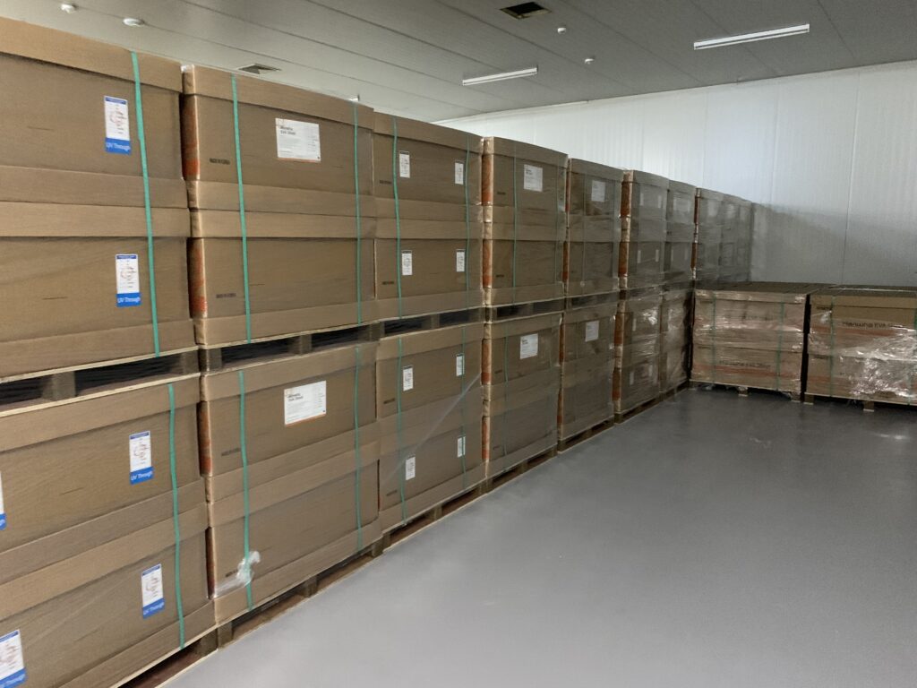
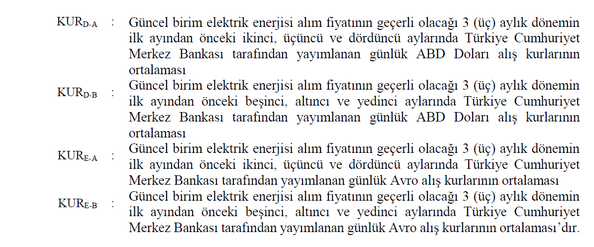
Certified solar panels indicate that the solar panel manufacturer meets the quality and safety requirements of the certification bodies on the specified product. However, this approval is only possible if the specified raw materials are used and if these raw materials are stored in the warehouse in the correct climatic values.

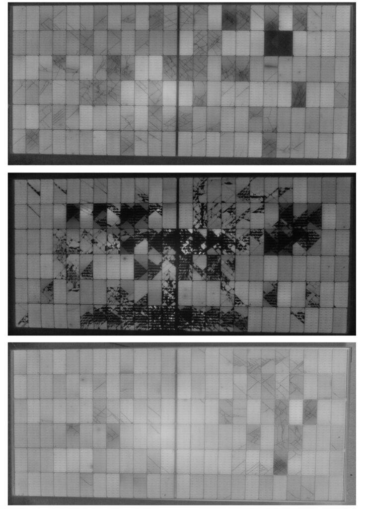
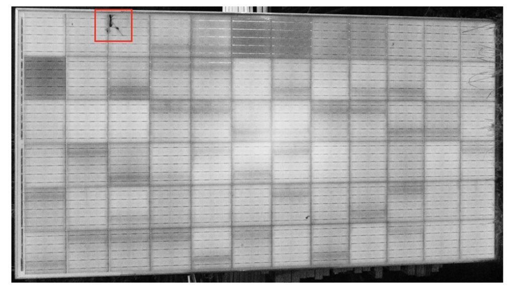
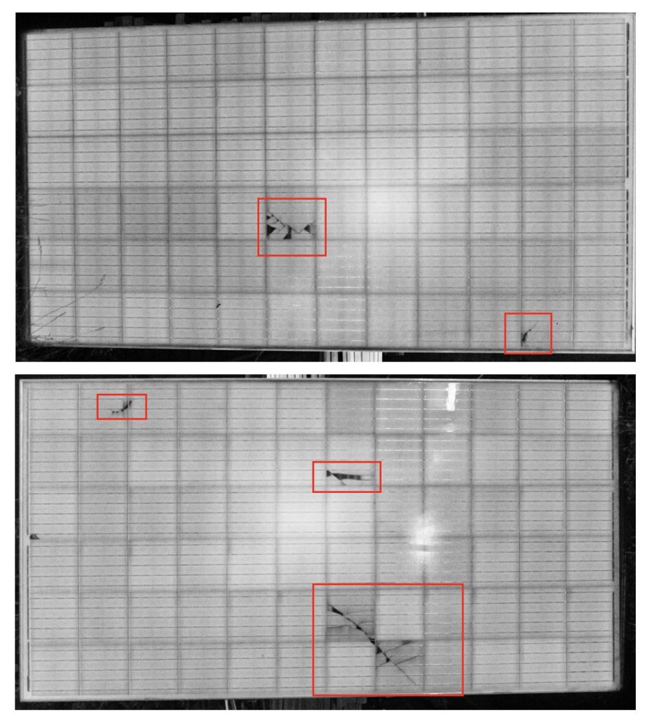
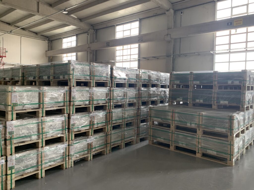
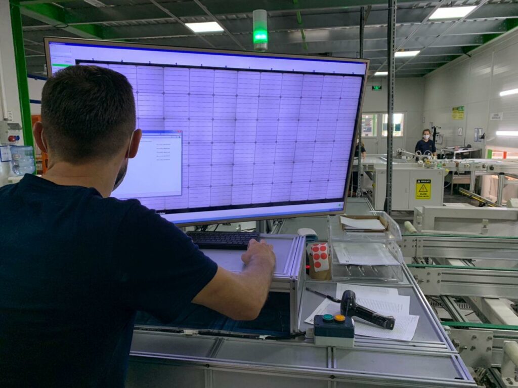
If the inspection is not carried out at the solar panel factory, the possibility that the solar panels have physical defects causes the lifetime of the solar panels to decrease. In mass production factories, it is very important that the production line is controlled by an outside eye. In addition, not all solar panels produced have the same electrical values. Solar panels that provide the committed values for the project must be selected and prepared for shipment.

Visual inspection of solar panels before packaging
Visual control in the production phase

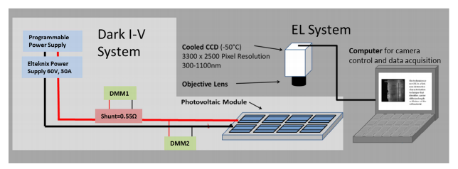
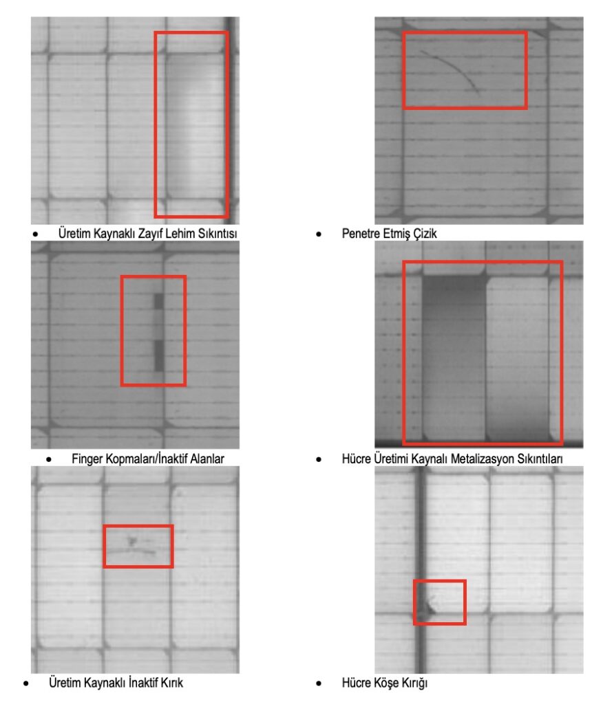
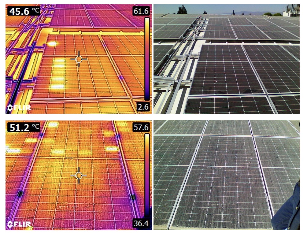
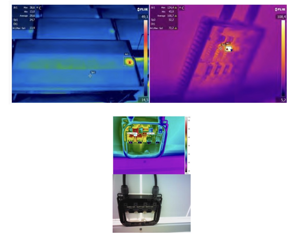
Not all defects of solar panels can be visually appreciated, THE visual control must be performed by experts. According to the determined acceptance criteria, the solar panels suitable for the project must be inspected, selected and prepared for shipment.

EL control in solar panel production
EL control in the production phase

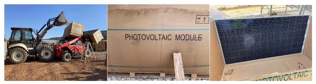
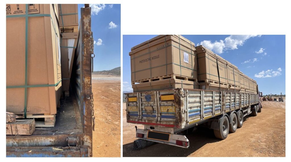
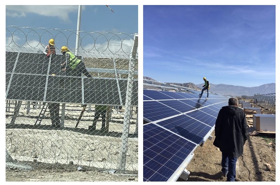
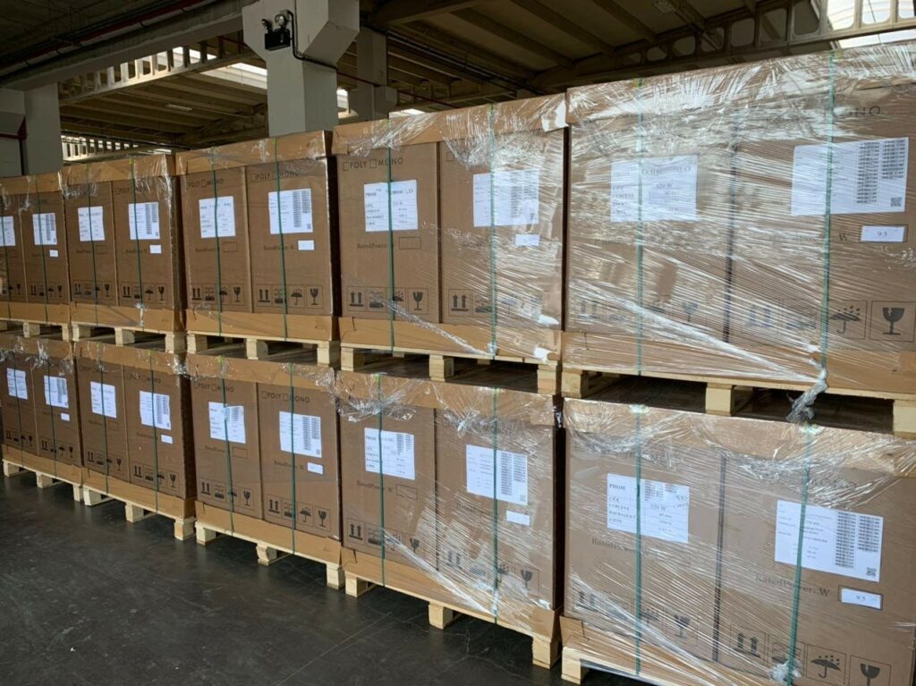
Preparation for shipment is the last stage in the procurement of solar panels with a high probability of error. It is very important to determine the precautions to be taken to eliminate the risks of physical damage during the transportation of solar panels to the field and to carry out the manufacturing inspection of PV modules in this process.

Packaging inspection in solar panel manufacturing
After packing the manufactured solar panels, they are checked until they are loaded
.

If you want to ensure the quality assurance of the solar panels to be produced for your project, you can contact us. Solarian’s engineering and inspection team is ready to support you on manufacturing inspection during the production of solar panels.

Fill in the contact form to get in touch with us.

Solar Panel Types and Advantages

Solar panels, most commonly used in commercial or residential installations, are divided into three types: monocrystalline silicon, multicrystalline silicon and thin film. Here is a brief description of each:

(1) Single-crystal silicon: Most efficient

Monocrystalline solar panels are often touted as the most efficient option for large energy systems on commercial and residential properties. But panel sizes can vary; therefore, single crystals can also be used for small devices.

Advantages

– Because they are made of high-purity silicon, their efficiency increases by 15% to 22%.

– They do not require larger areas than polycrystalline and thin film panels.

– Single crystal panels can be used for more than 25 years as they have the stable and inert properties of silicone.

Disadvantages:

– Because of its complexity and high price.

– Snowfall is not a suitable option for cold climates as it can damage solar cells and cause system failures.

(2) Polycrystalline silicon: The most economical

As the name suggests, multicrystalline solar panels consist of multiple pure silicon crystals stacked together. However, more crystals does not always mean better.

Multicrystalline panels are actually less efficient than monocrystalline panels. However, the power options from 5W to 250W and higher are ideal for small and large installations.

Advantages

  • They are cheaper than single crystals because the manufacturing process is simpler.
  • The melting process produces less waste and is environmentally friendly.
  • Durable, like monocrystalline solar panels, they are a good option for budget-friendly homeowners.

Disadvantages:

  • Low efficiency (13% to 17%) because the silicon used is of low purity.
  • It occupies the same amount of space as a single crystal battery to produce the same power level.

(3) Thin film: Recommended to provide energy for transportation

Although lightweight and easy to transport, silicon-free thin-film photovoltaic cells are the most inefficient type of solar panels. Use them only for installations that don’t require a lot of power generation; flexibility and portability are two key factors of this type.

Advantages

– Easier production and lower costs.

– Ideal for solar-powered transportation applications such as panels mounted on bus roofs or refrigerated trucks used for cooling.

Disadvantages:

– Rooftops are not a good option as they require too much space to generate enough solar energy.

– They are weaker than crystalline panels, so they have a faster degradation time. Membrane panel installations only provide a short-term guarantee and homeowners should consider this, especially depending on how long they will be in the home.

How to Avoid Weld Strip Deviation During the Production of Solar Panels?

The problem of weld bead deflection during the welding process of photovoltaic cells cannot be ignored; this is a problem that operators must pay attention to in their work.

The welding position of the connecting strip must be straight and unbent; otherwise it is easy to cause welding strip deviation, resulting in the welding effect not being as desired.

Therefore, during normal operations, operators must straighten the weld strip before starting welding, making sure that the weld strip is flat and completely covers the weld stress line of the solar cell and does not create any exposure.

Considerations to avoid welding strip deflection (exposure):

  1. Deviation between the positioning of the connecting strip during welding and the weld stress line position of the solar cell;
  1. Excessive temperature causes the weld strip to bend, leading to bending of the solar cell after welding is complete;
  1. In the process, the starting point of the connecting strip deviates, which can cause the weld to be skewed and result in bends in the middle or misalignment at both ends.

Measures can be taken to effectively prevent weld bead deflection (exposure). The position of the solar cells on the base plate must be fixed to prevent deflection.

The main grid of the raw material used for solar cells causes the weld strip to deviate from the main grid after welding.

During the welding process, it should be borne in mind not to use abnormally deformed connecting strips of the welding strip.

Operational standards must be strictly adhered to, routine operations must be carried out according to specified requirements and care must be taken in the selection of connecting strips.

Photovoltaics – Question and Answer

Question: What is the Principle of Photovoltaic Power Generation?

Answer: The basic principle of solar photovoltaic power generation is to directly convert solar energy into electrical energy using the photovoltaic effect of solar cells, that is, the photoelectric effect of semiconductors.

When sunlight strikes a metal or stone containing semiconductor materials such as silicon, the electrons in the silicon crystal turn into free electrons after absorbing the sunlight. When the energy absorbed by the electrons is large enough to overcome the internal gravity of the object, they do work, escape from the surface of the object and become photoelectrons.

When atoms with different numbers of outer electrons are doped into pure silicon, P-type semiconductors and N-type semiconductors can be created. When P-type and N-type are combined, the contact surface creates a potential difference, becoming a solar cell.

When sunlight hits the P-N junction, holes move from the P-polar region to the N-polar region and electrons move from the N-polar region to the P-polar region. At this point, current is generated and this is the principle of photovoltaic power generation.

It follows from this that N-type silicon and P-type silicon are in fact the basic components of solar photovoltaic panels. In practice, solar photovoltaic panels composed of N-type silicon and P-type silicon are installed in centralized or distributed solar power plants and become a small interceptor that collects sunlight and continuously supplies electrical energy.

Question: Do you understand the relationship between solar power generation and photovoltaic power generation?

Answer: There are actually two types of solar power generation, one is solar thermal power generation and the other is solar photovoltaic power generation. Solar thermal power generation is the process of converting solar energy into thermal energy through water or other devices and then converting the thermal energy into electrical energy to provide power, which is called solar thermal power generation.

Solar photovoltaic power generation is a power generation method that converts light energy directly into electrical energy without the need for thermal processes. These include photovoltaic power generation, photo-chemical power generation, photo-induced power generation and photobiological power generation.

Photovoltaic power generation can actually serve as a representative of solar photovoltaic power generation, and compared to solar thermal power generation, photovoltaic power generation devices are simpler.

In general, photovoltaic power generation, which is part of solar photovoltaic power generation, has more advantages over solar thermal power generation.

Dimensions of Solar Panels

There are two common configurations of conventional solar panels, 60 solar cells and 72 solar cells . Depending on this, their dimensions are:

Photovoltaic module of 60 solar cells: 1,635 square meters (1.65 meters x 0.991 meters)

Photovoltaic module of 72 solar cells: 1,938 square meters (1,956 meters x 0.991 meters)

Note: Larger and more efficient photovoltaic modules are currently available on the market. In this article, a photovoltaic module with only 60 solar cells and a photovoltaic module with 72 solar cells are used as examples.

When you decide to install photovoltaic systems, one of the first questions people ask is,“Where should I install the system?” Solar panels take up a significant amount of space and not every roof has enough room to accommodate them.

This article will cover standard solar panel sizes and explain how to determine how many solar panels you need for your photovoltaic system. The photovoltaic capacity can then be calculated to estimate annual energy production and revenue.

Solar cells are the smallest unit of photoelectric conversion and are usually used with dimensions of 156mm x 156mm. The operating voltage of solar cells is about 0.5V and generally cannot be used alone. After solar cells are packaged in series and parallel, they become photovoltaic modules.

A single solar cell is 156mm x 156mm square. A panel of 60 solar cells consists of a 6 × 10 grid pattern. A panel of 72 solar cells consists of a 6 × 12 grid pattern and is approximately 3-4 centimeters high.

Note: The commonly used solar cell sizes currently on the market include 166, 182, 210 and other specifications.

How many solar panels can I place on my roof?

roof with solar panels on it

At present, high power solar panels such as 490W, 535W, 550W are generally used in the domestic photovoltaic market.

The use of high-power solar panels on limited roof space improves utilization efficiency and increases energy production revenue per unit area.

The available area of your roof determines the maximum capacity of a photovoltaic power plant you can install. Based on the available photovoltaic module power, a 1KW installation requires approximately 8 square meters of space;

If you want to install a 15KW photovoltaic power plant, approximately 100 square meters of roof space will be required.

If we want to build a 15KW household photovoltaic power plant, the use of high power solar panels and low power solar panels can be as follows:

15000W/490W ≈ 30 pieces

15000W/330W ≈ 45 pieces

Below we will compare the roof area covered by the photovoltaic array between low power solar panels (330W) and high power solar panels (490W):

330W solar panel size: 1855*1092*40mm

490W solar panel size: 2187*1102*35mm

In general, a standard domestic solar system covers 100-200 square meters of roof space. The system can be installed on your roof or on a ground bracket elsewhere on your property (such as a bungalow or caravan). The exact size will depend on the wattage of the solar panel and the array layout.

How many volts output does a portable solar panel have?

portable solar panel

If you purchase a boat or motorhome in the future, choosing a suitable solar panel will significantly extend your fun time. While some standard-sized solar panels are installed on individual vehicles or vessels, most vehicles and vessels do not have the space to install them, so smaller solar panels are needed to accommodate. Typically, these smaller solar panels have a standard 12 volt or 24 volt output.

What is the weight of the solar panel?

Besides the size of solar panels, people often ask about the weight of solar panels. Solar panels can be heavy and lifting them onto the roof can be a challenge, especially when working alone. Based on experience, the weight of solar panels usually ranges from 18 to 35 KG.

Electroluminescence (EL) Imaging in Solar Panels

Electroluminescence Imaging, Electroluminescence (EL), an optical and electrical phenomenon, refers to the state of emitting light in response to an electric current or very strong electrical field passing through the material.

It is of great interest among photovoltaic panel quality tests as it detects serious defects that are invisible to the eye and cannot be detected by thermal imaging. It is performed to detect damages that occur during the manufacturing, assembly or transportation of solar panels on a cell-by-cell basis.

Review Mechanism;

Electroluminescence has the same concept as a light emitting diode (LED). This test, which is an X-ray of the solar panels, enables early detection of existing resistive parts and defects that may cause problems in the future.

Electroluminescence Photography Device

As shown in the image above, a power supply is connected to the solar panel in a closed and dark area, providing the appropriate voltage to reach the short-circuit current. The panel is then photographed with a camera at a fixed distance from the solar panel and the image is then analyzed using a special program.

What defects and problems can we detect with electroluminescence?

  • Microfractures
  • Production Defects.
  • Defects due to Shipment.
  • PID.
  • Corrosion
  • LETID.

The cells produced today are less than 200 micrometers (µm= 1*10-6) thick. These cells are therefore inherently fragile. They must be handled with care and precision.

There are many reasons for micro-fractures in photovoltaic cells.

So what is the cause of these fractures that are invisible to the naked eye?

  1. The solar panel is in the manufacturing phase;

Micro-fractures can occur in many stages such as cell cutting, cell stringing and soldering processes.

Solar panel manufacturers check with Electroluminescence imaging to detect these cracks in two stages, before and after the lamination process as part of their quality assurance procedures. Based on the inspection results, they classify the panels according to their internal quality standards.

In addition to microfractures, it is also possible to detect other defects. The table below summarizes the most common types of defects.

Solar Panel Damage Weak Solder Weak Solder Crack Penetrated Scratch
Damage Types in Solar Panels
  • During shipment and transportation;

Micro-fractures can occur when the panels are shipped from the production factories to the project site. This is because the panels are packed with incorrect packing methods or the instructions in the transportation manual specified by the manufacturer are not followed.

Damage caused by forklifts during transportation of solar panels
Damage caused by forklift during transportation
Damage during transportation of solar panels
Solar Panels in Transit
EL images of solar panels damaged during transportation
EL images of panels damaged during transportation
  • During the installation phase;

They may occur at the project site during the unloading of panels or during the assembly of panels.

Damage to solar panels during the installation phase

The El images that resulted from the inspection we performed after the installation are as follows. As can be seen, there are many branched/active fractures in the panels that may cause power drop.

EL images of solar panels damaged during installation
Hand images of panels damaged during installation
EL images of solar panels damaged during installation
Hand images of panels damaged during installation
  • Maintenance and operation phase;

There are many factors such as the use of inappropriate cleaning methods for the panels, maintenance and operations personnel standing/walking on the panels or other environmental conditions.

  • High wind speed.
  • Hard falling hail
  • Heavy snow load
  • Temperature difference between day and night (thermal cycle)

Problems Caused by Micro Fractures

Identifying the problems caused by micro-fractures, the reasons for their occurrence, the impact on the efficiency of the panels or the project as a whole is one of the complex issues in SPP projects, as it depends on many details and technical issues.

From the manufacturer’s perspective, the presence of a micro-fracture in a panel does not necessarily mean that the entire panel is damaged or unsuitable.

Panel manufacturers evaluate panels according to internal quality standards, taking into account the path (shape) and number of micro-fractures, and whether these fractures interfere with the passage of current in some parts of the cell, and whether the damaged parts should be isolated from the photovoltaic cell.

Micro-fractures leading to in-active areas have a direct impact on the production of the cell and therefore on the productivity of an entire panel. In addition, they will cause mismatch losses between arrays (Mismatch Loss).

Micro-fractures that lead to the isolation of part of the cell cause the appearance of Hot Spots, which means that the temperature of the isolated part of the cell rises to high temperatures and

  • Backsheet degradation
  • Delamination
  • Power degradation

will lead to many different problems.

Micro-fractures can expand and propagate depending on the operating conditions of the panels in the field, wind/snow load, mechanical stresses of the panels and panel temperature differences.

Global Standards in Electroluminescence Imaging

  • IEC TS 60904-13:2018

Author:

Betül Halil
Betül Halil

Thermal Imaging in Solar Panels (PV)

PV THERMAL IMAGING

Photovoltaic solar panels constitute a large part of the solar power plant investment amount. At the same time, many performance and safety tests are applied to these solar panels by the relevant laboratories as there are many types of defects that cannot be seen by the eye.

Unlike many other inspection methods, the use of thermal imaging in photovoltaic systems allows the identification of problem panels and cells while the system is in operation; thermal imaging does not require disconnection of the system or any part of it, as it can be performed under normal operating conditions. In addition, thermal inspection can be performed in a shorter time than other inspection methods.

What are the Advantages of Thermal Examination?

  • Quality Assurance of Photovoltaic Panel Installation

The quality of photovoltaic panels may vary from manufacturer to manufacturer or even from batch to batch for the same factory. Photovoltaic panels may come out of the factory without any defects and problems, but problems and defects occur even during shipment to the field due to improper loading on transportation vehicles.

The quality of the installation also depends on the skill and competence of the EPC team deployed by the contractor. In short, thermal imaging is one of the easiest ways to keep track of the panels produced, shipped and installed.

  • Preventing Electrical Efficiency Losses

When preparing the financial feasibility studies of SPP projects, the project lifetime is assumed to be between 20-25 years and the gradual decrease in the efficiency of the panels is taken into account in such studies. However, as we mentioned in detail earlier, it is difficult to predict the problems that may occur in the panels during transportation and installation or various problems that may occur in the panels during operation and maintenance.

Therefore, a thermal inspection of the stations should generally be carried out at regular intervals to ensure that the stations operate efficiently and are free from faults. For example, every 6 months or once a year. This check is considered one of the routine checks performed by the operation and maintenance (O&M) team.

  • Fire Risk Reduction

Thermal imaging in SPP projects is not limited to photovoltaic panels. It is possible to detect and identify any temperature increase in any component of the system with thermal inspection. For example, thermal imaging of electrical panels can detect any problems in cable connections that may cause high temperatures or electrical sparks that may cause fire.

A thermal image showing the high temperature of the electrical wiring inside the enclosure.
  • Fast Identification of Problems

Thermal imaging enables rapid detection and investigation of problems without the need for contact. Most modern thermal cameras record two images, one thermal and one visual.

By-pass diode faults in panels

What kind of defects can we detect with thermal inspection?

Thermal imaging aims to identify where there are anomalous temperatures, i.e. where there is a clear temperature difference between one region and another with the same characteristics. Areas with high temperatures in photovoltaic panels are called “Hot Spots”.

So how are these hot spots formed?

Hot spots can simply be caused by shadow falling on solar panels and cells or by manufacturing defects.

  • Broken glass

Fractures in the glass of the photovoltaic panel cause the cells to overheat.

The Effect of Broken Glass in Solar Panels
  • Shadowing:

Shading is the most common cause of high operating temperature of panels. For example; grass, trees, bird droppings, surrounding tall buildings and poles, etc.

Hot-Spot Failures due to Shading in Solar Panels
  • Production-related problems:

One of the reasons for the high temperatures of photovoltaic panels is defects in the production phase. For example, cells of different efficiency used in the same panel, active and inactive fractures in the panel, poor soldering of ribbons. All such defects will cause hot spots in photovoltaic panels in the long run.

Manufacturing Hot-Spot Problems in Solar Panels
  • Overheating of By- Pass Diodes

The junction boxes of PV modules are slightly hotter than the rest of the module. This temperature is caused by overheated bypass diodes inside the junction box. To reduce the effect of shading on the panels on the generation, a bypass diode is connected in parallel and of opposite polarity to an array of solar cells. Under normal operating conditions, the bypass diodes are in reverse polarity mode, i.e. inactive. However, if there is a mismatch between the cells or partial shading affecting the PV panel, the bypass diode switches to forward polarity mode and becomes active. For example, it allows current to flow through it and not through the shaded cell. Therefore, the temperature of the diode when it is active is higher than that of inactive diodes.

By-pass Diode Induced Failures in Solar Panels
  • Overheating of electrical panel connections

Large-scale SPPs usually use centralized inverters with DC collection boxes. Collection boxes are used to collect individual DC strings and connect them to a single larger cable. These aggregation boxes often have thermal problems due to improper wiring, internal cross and loose wiring.

Overheating of Connections in Electrical Panels

Global Standards in Thermal Imaging

IEC 62446-3 is the standard that determines many environmental conditions and specifications such as equipment (thermal camera), minimum radiation, maximum wind speed to be used in thermal inspection.

The IEC 60904-12-1 standard covers the specifics of thermal inspection of photovoltaic panels in laboratories or production lines, but does not address grid-connected installed SPP system inspections.

Can We Detect All Problems in Panels with Thermal Imaging?

Thermal imaging only detects problems that cause high temperatures. But defects that have not yet caused a temperature rise cannot be detected by thermal imaging.

These undetected defects are often micro-fractures in photovoltaic panels. Electroluminescence imaging can detect these fractures before they become hot spots. We will talk about such examinations in detail in a new article.

Sources:

IEC 62446-3

Report IEA-PVPS T13-10:2018

Author:

Betül Halil
Betül Halil

YEKA SPP-3 (Mini YEKA) Price Analysis from 2021 to 2022

In May 2021, within the scope of YEKA SPP-3, a total of 1000MWe SPP capacity allocation competition was finalized with 74 different projects in 36 different provinces. You can find all the details about the competitions here. According to the specifications, the winning price is revised every 3 months according to the following formula in the specifications.

According to the formula, the winning price started to operate in July 2021. The first change occurred in October 2021 and the second change occurred in January 2022. Based on the initial price as index value, there is an increase of 17.76% in TL terms and a decrease of 25.33% in USD terms as of January 2022.

If we consider the winning bid as 25kr/kWh, the sample price change is as follows.

Year Moon kr/kWh TL % $cent/kWh USD %
2021 July 25.00 – 2.90 –
2021 October 26.66 6.63% 2.92 0.48%
2022 January 29.44 17.76% 2.18 -25.33%
  • « Go to Previous Page
  • Page 1
  • Interim pages omitted …
  • Page 3
  • Page 4
  • Page 5
  • Page 6
  • Page 7
  • Interim pages omitted …
  • Page 9
  • Go to Next Page »

SOLARIAN